I’ve been intending to deploy NSX-T 2.4 since it’s release a few months ago to check out what’s new.
With that, I learned a little about a repeatable workflow to deploy it in a relatively easy way.
Let’s get started
This assumes you already have your vCenter deployed with a vSphere cluster and port groups set up. For NSX-T 2.4 (-T hereafter), you don’t have separate controllers from your manager, you can deploy a single manager and then add additional managers to make it a cluster. You’ll want 1 or 3 NSX Managers, depending if this is a lab, testing, or production; and if it’s a cluster, you’ll likely want an additional IP to serve as the cluster VIP. If you’re keeping count, that’s four (4) IPs, which is how I’m going to deploy it.
First, download the OVA, deploy it into your cluster and power it on. Give it a few minutes to boot up and initialize all the services. Once it’s up and running, log into the IP you provided during the OVF wizard, you’ll see a nice “Welcome to NSX-T” splash screen:
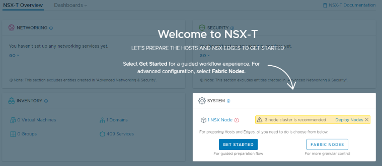
Let’s take a look by clicking Deploy Nodes:
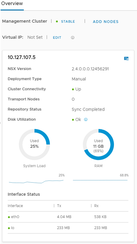
Here you can see your manager is stable, DO NOT CLICK ADD NODES YET. We need to add a place for those additional nodes.
You should be in the System section at the top, with Overview selected on the left, click Fabric to add a Compute Manager (vCenter), then click +ADD. Provide the display name, FQDN or IP, admin credentials, click add, then accept the thumbprint.
*Note: If you’ve played with NSX-T previously, you may be greeted by an error, you need to click Resolve:
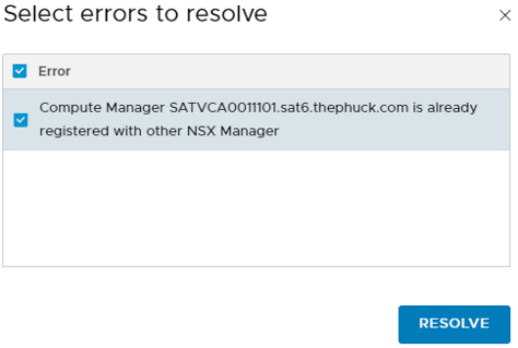
Wait for Registration Status to show as Registered. You may have to scroll down and click Refresh (it’s sometimes off the screen at the bottom). Once Connection Status says Up, go back to Overview on the left.
Now it’s time to add additional nodes to our management cluster, so click ADD NODES. For consistency, provide the same credentials, validate all settings, select your desired size, and click Next. Under Nodes, fill in the info for Node 2 (Resource & Host aren’t required), then click ADD NODE to add the 3rd one simultaneously:
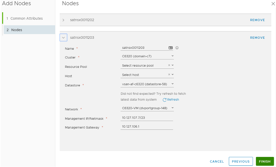
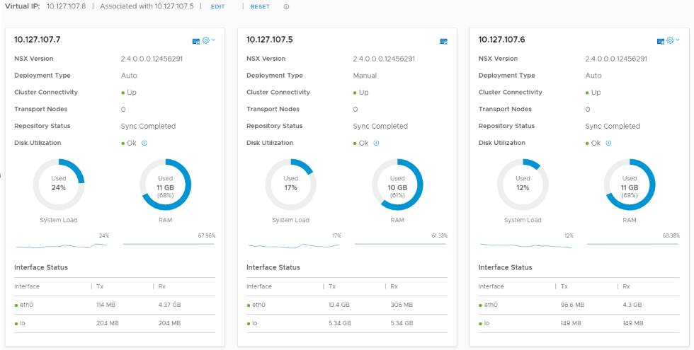
Click FINISH and let it deploy the two additional nodes. You can watch the OVF deployment in the vCenter tasks, and the NSX UI for the status of each, which this may take some time. Once it’s done and everything shows up & stable, click EDIT for the Virtual IP to add your VIP. It should look like this:
Creating Profiles
The next step is creating profiles for uplinks, virtual switches, transport nodes, etc, all the things you’ll need to get started. You can go through the wizard and add them on-the-fly, but I prefer to lay out everything up front.
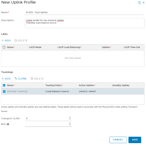
If you’re not there already, navigate to System > Fabric > Profiles, then select Uplink Profile at the top. Let’s create an uplink profile for your N-VDS, I set the teaming policy and added “vmnic0” and “vmnic1” to the active uplinks. You can set this however you intend:
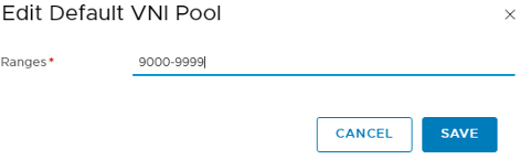
Now let’s set our VNI Pool by clicking Configuration on the top right (you could leave this default, but I choose a VNI Pool outside of my -V setup):
Transport Nodes
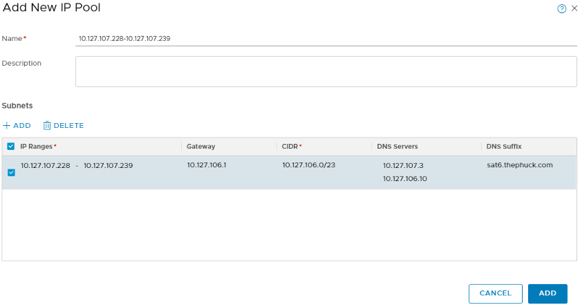
You can use DHCP for your Transport Nodes (think VTEP vmkernel ports in a prepared cluster in -V), but I prefer to create an IP Pool. You will need an IP for each uplink you plan on assigning to the profile we created previously. For instance, I have a 6-node cluster with dual uplinks, so my pool is 12 IP addresses. Navigate to Advanced Networking & Security > Inventory > Groups > IP Pools to create the pool:
Just like -V, you will need to create a Transport Zone. For this, we need to go to System > Fabric > Transport Zone and click +ADD:
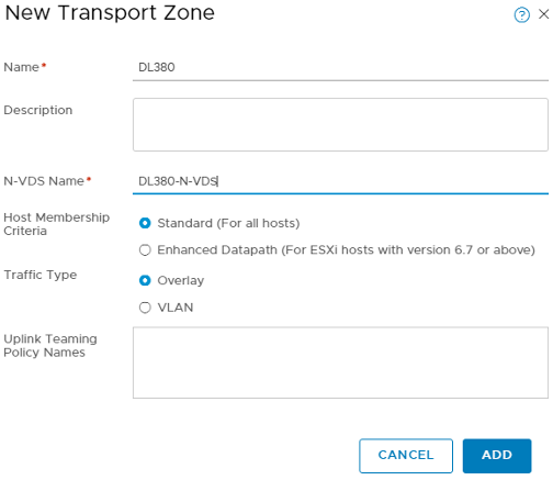
This is what creates the new vSwitch, or N-VDS, for -T, so name it accordingly.
Now we need to create a profile for our Transport Nodes. You assign this profile to your hosts to have them join the transport zone, and subsequently the N-VDS. Since you should already be in System > Fabric, select Profiles > Transport Node Profile and add one:
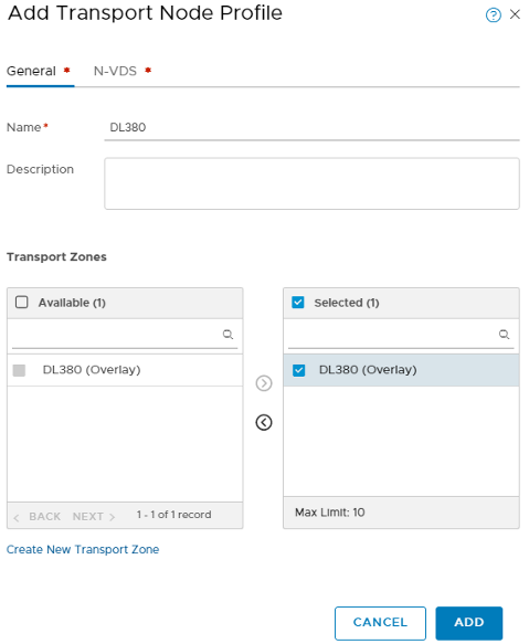
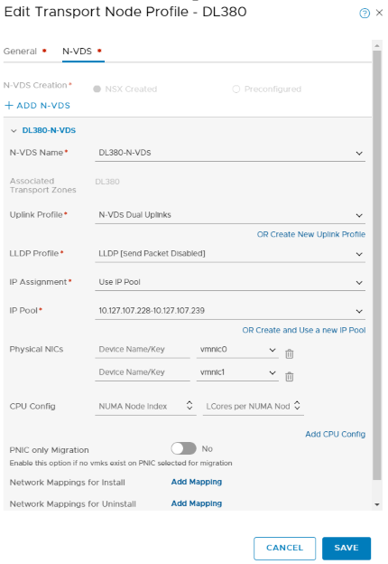
Select the newly created Transport Zone and click the > to move it over to selected. Before clicking ADD, you’ll need to select the N-VDS tab and associate the new N-VDS to the Transport Zone. Here’s where we select which N-VDS to use, the previously created Uplink Profile, along with the IP Pool we previously created:
Almost there!
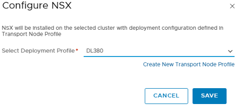
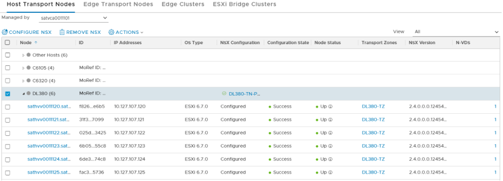
Now that we’ve set up the framework, it’s time to apply that to actual ESXi nodes. This step is what actually “prepares” the hosts and makes them available to -T, similar to the process in -V. You should still be in the System > Fabric section, so select Nodes > Host Transport Nodes. From here, you’ll likely need to change Managed by to the vCenter/Compute Manager we added at the beginning. You should see your hosts & clusters inventory now. Here, I select the checkbox for the cluster I wish to add, you could easily select individual ESXi hosts for this, as well. When selected, click Configure NSX and select the Transport Node Profile we created earlier. This installs NSX-T, joins it to the Transport Zone, and creates the N-VDS on the ESXi node(s), and sets up everything based on the profiles we’ve created along the way:
While you’re monitoring the installation progress, remember to scroll down & hit the REFRESH button that’s often off the screen. When it’s done, Configuration State should say Success and Node Status should say Up, along with the Transport Zone(s) and NSX Version:
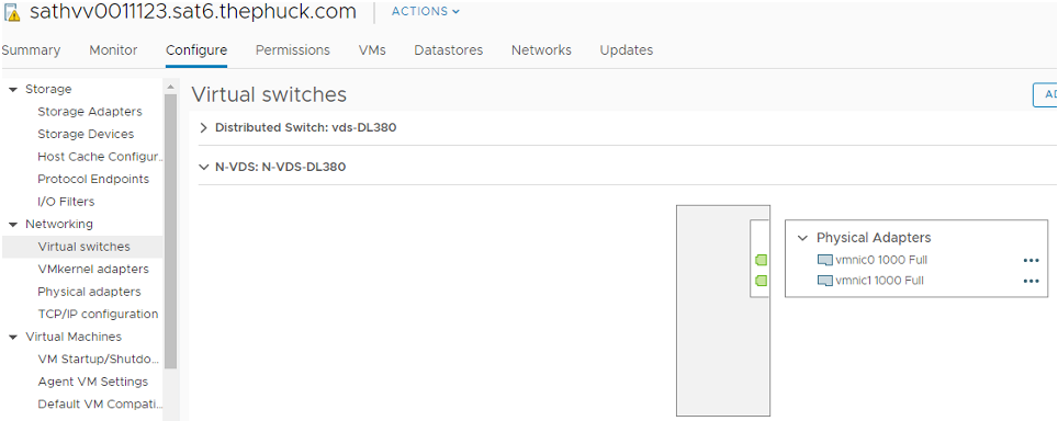
From here, you should be able to hit the vSphere Client to see the new N-VDS:
However, the VMKernel ports won’t show up. You’ll have to SSH into your ESXi host for that:
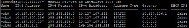
Notice something a little odd? Yeah, so, vmk10 & vmk11 are the two uplinks we assigned to the N-VDS, but what about vmk50? That’s called the “HyperBus” vmkernel interface used for containers. Now you can do PKS! Well, hopefully that’s going to be a future blog post, but at this point we’ve laid the foundation to start playing with NSX-T.
What did I just do?
Congratulations on deploying NSX-T! What you did was lay the foundation to start playing with NSX-T in your environment. It behaves a little different than -V, you can add VMs to any new logical switches, or Segments, you create, but there are some considerations that you need to be aware of. If you want to allow these VMs to talk out, you’ll need to create a Transport Zone that’s VLAN-backed and matches your native network (VLAN ID 0 doesn’t tag a VLAN), and a subsequent VLAN-backed Segment. From there, you’d create a Tier-0 Gateway that would behave like an ESG that’s connected to a regular port group on it’s uplink with a Logical Switch connected as an internal link.
In order to set that up, you’d follow the same process, but create an additional Transport Zone, you’ll need to select the Traffic Type to VLAN for that Transport Zone. If you only have two uplinks per ESXi host, you’ll also need to make sure the N-VDS tab of the Transport Node Profile has only a single uplink for each N-VDS (one N-VDS for the overlay transport zone and one for the VLAN transport zone). What I ended up doing (after I created all these screenshots) was create a single profile with both Transport Zones and two N-VDSs. Next, you’ll need to create a VLAN-backed Segment to attach a Tier-0 Gateway’s uplink to, then, an overlay Segment behind it. However, before you do all that, you’ll need to create some edges, associate those to your edge profile we created, and create an edge cluster, associating these new edges. Hopefully that will be my next blog post…
Until then, I hope this deployment went well for you!
Great post – I am familiar with NSXv and have deployed it several times into production. NSX-T is pretty different and I can tell they’re backing the documentation into the product rather than the opposite. The concept of a VLAN transport and Overlay transport still puzzles me. I want to figure that out as best as possible. Looking forward to your next entry – can you go into that as best you can?